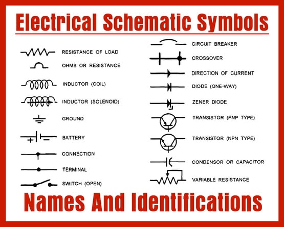
There are different country specific standards iec british ansi and as australian standard that define the symbols used in circuit diagrams across the world. Circuit symbols are used in circuit diagrams which show how a circuit is connected together.
 Basic Electrical Schematic Symbols Wiring Diagram Shw
 The standard electrical symbols are smart industrial standard and vector based for electrical schematic diagrams.

Electrical schematic symbol. The presentation of the interconnections between circuit components in. There are some standard symbols to represent the components in a circuits. 52 ac circuit breaker 53 exciter or dc generator relay 54 high speed dc circuit breaker 55 power factor relay 56 field application relay 59 overvoltage relay 60 voltage or current balance relay 62 time delay stopping or opening relay 63 pressure switch 64 ground detector relay 65 governor 66 notching or jogging device.
The actual layout of the components is usually quite different from the circuit diagram. There are many electrical and electronic schematic symbols are used to signify basic electronic or electrical device. Electrical symbols and electronic circuit symbols are used for drawing schematic diagram.
926 electrical schematic symbols of electrical engineering solution. Electrical symbols electronic symbols. Electrical symbols electronic symbols in pdf the largest collection of symbols in the network in pdf formatfor consultation and interpretation of components devices and electrical and electronic circuit.
Electrical symbols are used to represent electrical and electronic devices in schematic diagrams. Most of electrical symbols can change their appearance style and color according to the requirement. An electronic symbol is a pictogram used to represent various electrical and electronic devices or functions such as wires batteries resistors and transistors in a schematic diagram of an electrical or electronic circuitthese symbols are largely standardized internationally today but may vary from country to country or engineering discipline based on traditional conventions.
A circuit diagram electrical diagram elementary diagram electronic schematic is a graphical representation of an electrical circuita pictorial circuit diagram uses simple images of components while a schematic diagram shows the components and interconnections of the circuit using standardized symbolic representations. Electrical engineering solution includes the set of electrical engineering samples which can be not only viewed but also edited in conceptdraw diagram its convenient to use the predesigned electrical symbols from 26 libraries. This article gives some of the frequently used symbols for drawing the circuits.
However today most of the symbols are internationally standardized. These are mostly we used for draw circuit diagrams. The symbols represent electrical and electronic components.
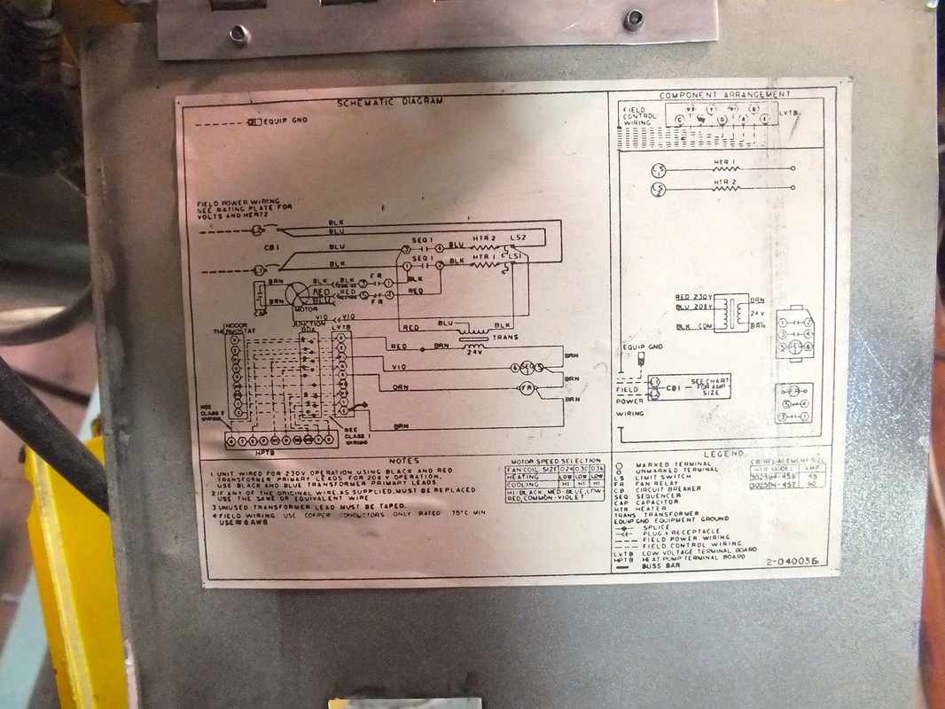
 Furnace Wiring Diagram Wiring Diagrams Dash
  Home Wiring Symbols Wiring Diagram
  Electrical Engineering Diagram Symbols Home Wiring Diagram
  Air Diagram Symbols Wiring Diagram Img
  Schematic Diagram Symbols Schema Wiring Diagrams
  Wiring Schematic Symbols Wiring Diagram Perfomance
  Electrical Schematic Symbols Study Com
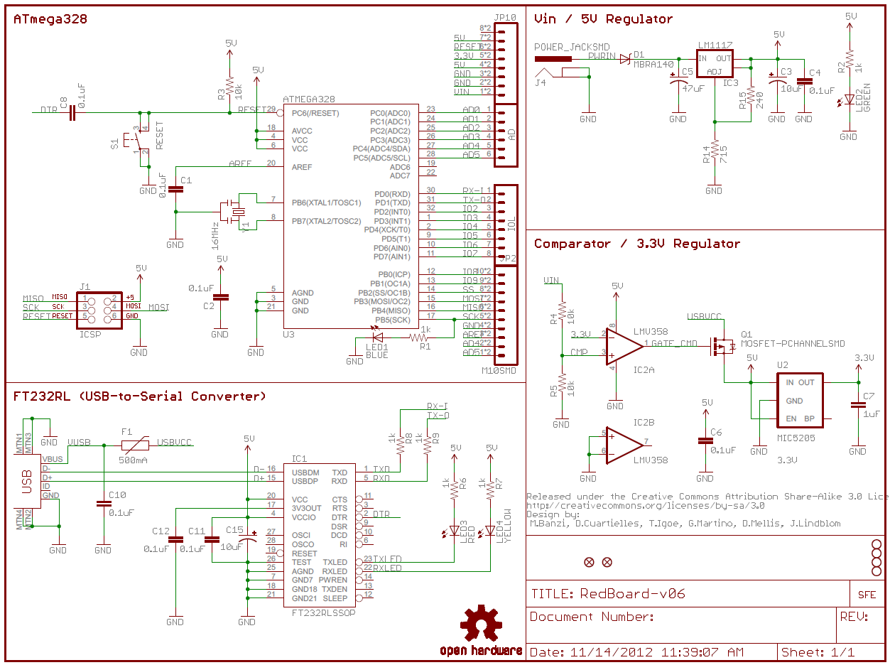
  How To Read A Schematic Learn Sparkfun Com
  Electrical Schematic Symbols Skinsquiggles Electrical Symbols