Traditionally these symbols may vary from country to country but today they are standardized. A final means of describing an electric circuit is by use of conventional circuit symbols to provide a schematic diagram of the circuit and its components.
 Electric Circuit Symbols Ausgrid
 A circuit diagram electrical diagram elementary diagram electronic schematic is a graphical representation of an electrical circuita pictorial circuit diagram uses simple images of components while a schematic diagram shows the components and interconnections of the circuit using standardized symbolic representations.

Electricity diagram. The symbols represent electrical and electronic components. We begin with a basics fuel pump relay diagram. So it has become quite easy to create schematic one line and wiring diagrams and blue prints containing shapes for switches relays transmission paths semiconductors circuits and tubes.
Electrical symbols and electronic circuit symbols are used for drawing schematic diagram. With smartdraw you can create more than 70 different types of diagrams charts and visuals. Click here to free download electrical diagram software.
Drawing electrical circuit diagrams you will need to represent various electrical and electronic devices such as batteries wires resistors and transistors as pictograms called electrical symbols. It shows how the electrical wires are interconnected and can also show. We begin with a basics fuel pump relay diagram.
Skip navigation sign in. Design circuits online in your browser or using the desktop application. Then you can use the built in electrical symbols to prepare and present your electrical diagrams in only a moment.
Visio professional 2019 visio standard 2019 visio 2013 visio professional 2016 visio standard 2016 visio 2010 visio 2007 visio online plan 2 visio premium 2010 visio professional 2013 visio standard 2007 visio standard 2010 more. Most of electrical symbols can change their appearance style and color according to the requirement. The standard electrical symbols are smart industrial standard and vector based for electrical schematic diagrams.
How to read an electrical diagram lesson 1 realfixesrealfast. A wiring diagram is a simple visual representation of the physical connections and physical layout of an electrical system or circuit. Circuit diagram is a free application for making electronic circuit diagrams and exporting them as images.
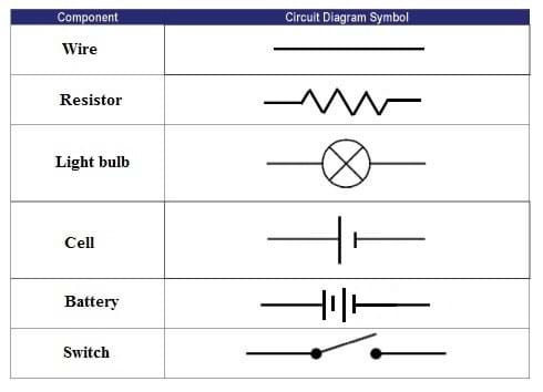
Create an electrical engineering diagram. Create an electrical engineering diagram. Some circuit symbols used in schematic diagrams are shown below.
The presentation of the interconnections between circuit components in. A single cell or other power source is represented by a long and a short parallel line. Electrical symbols electronic symbols.
 Circuits One Path For Electricity Lesson Teachengineering
 Electric Breaker Box Wiring Diagram Wiring Diagram Table
  Current Electricity Diagram Electricity Wiring Diagram Bookmark
  Electrical Panel Wiring Diagram Pdf Supercellule Fr What Is A Simple Electrical Circuit
  Wrg 4232 Electrical Panels Diagrams
  Bronco 2 Fuse Diagram Ford Ii Panel Wiring Schematics Electrical O
  Residential Electrical Panel Wiring Diagrams Operations Wiring